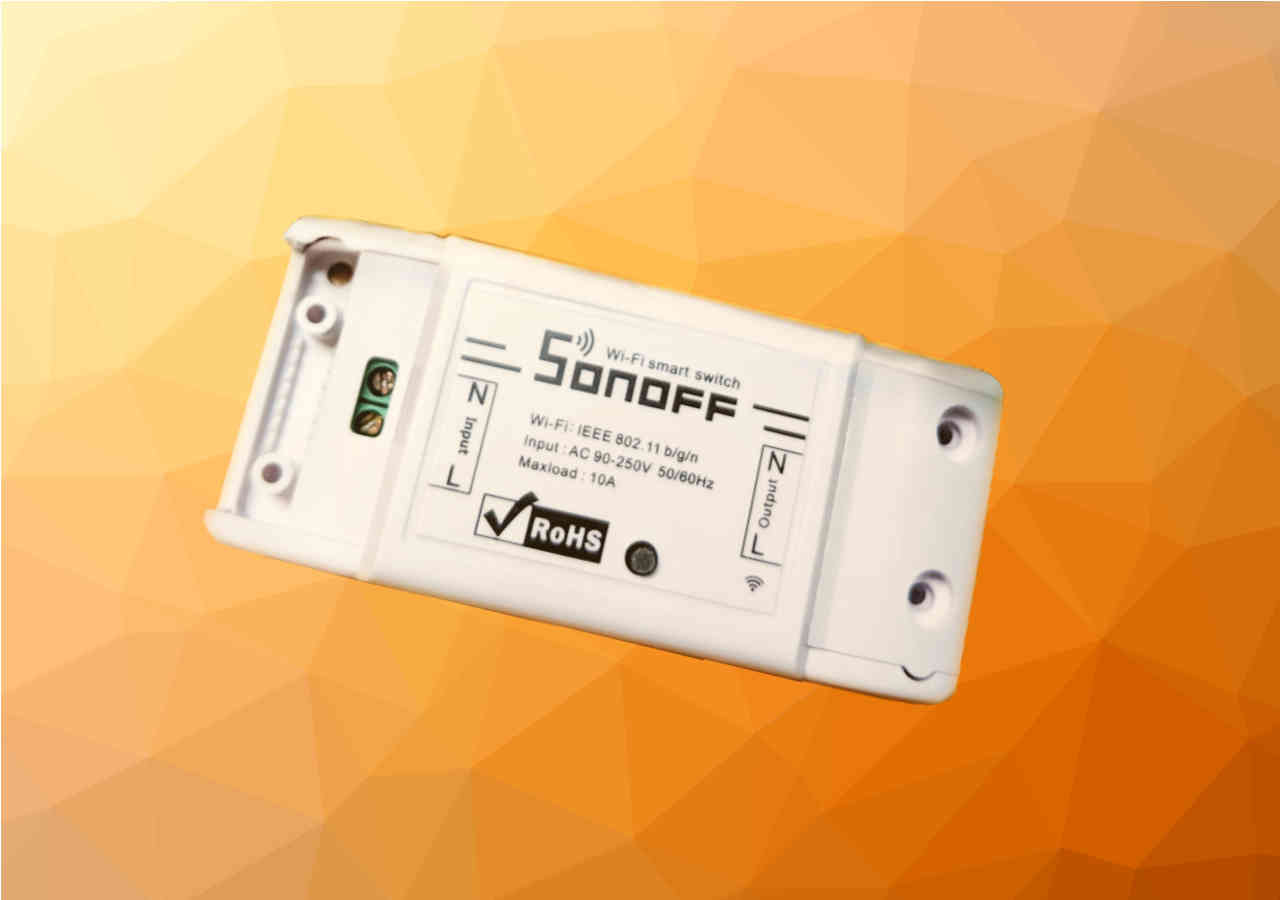
Over the weekend I flashed off the default firmware on a cheap Sonoff basic Internet connected relay. Along the way I ran into a few issues, but eventually got MicroPython running on it.
My father bought a bunch of SONOFF Basic modules and started installing them around his house. While I like the idea of them, I don’t like the idea of connecting them to some network off in Shenzhen, China. That has backdoor written all over it. Call me paranoid but any company operating inside China has a very real risk of being co-opted by their government. Opening it up you find that it is powered by an esp8266 and the serial connection is conveniently broken out for us.

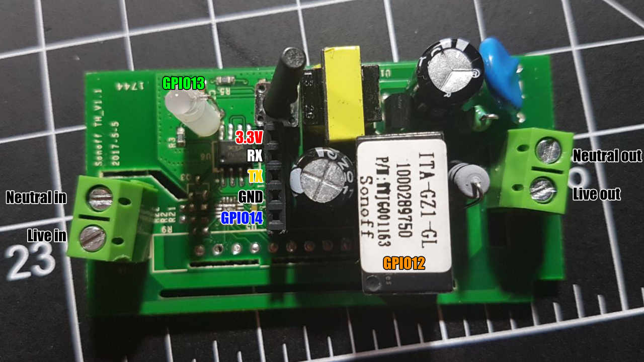
Soldering a little female header on there was quick and easy and then I had access to serial connection and GPIO14 which is free.
The GPIO
The button pin is GPIO 00. This is perfect because it lets us boot the esp into bootloader mode. The relay is connected to GPIO 13, and the LED is connected to GPIO 12
Folks, I’m going to tell you right now, mistakes were made. It took me FOREVER to figure out why my FTDI basic just wasn’t connecting to this thing. I broke out the multimeter, I made sure my voltages were correct, I reinstalled it to the outlet to see if it still powered on. swapped Tx and Rx. Nothing!… All I have to say now is, make sure you are connecting ground to ground and not “DTR GRN” to ground. GRN looks a lot like GND at first glance. I did however ensure my FTDI was in 3.3V mode. Make sure you do too!

CC BY 2.0 made available by Sparkfun Electronics.
Once that was sorted it was time to do a quick flash_erase and a flash_write of the new Micropython build for the 8266. Things should be smooth sailing from here. Let’s just do a quick erase_flash
1 |
esptool.py -p /dev/tty.usbserial-AD025KY2 erase_flash |
Perfect, and now we flash with esptool.py -p /dev/tty.usbserial-AD025KY2 write_flash 0x0 esp8266-20180511-v1.9.4.bin
1 |
esptool.py v2.3.1 |
Alright looks good and now lets screen into the serial port with screen /dev/tty.usbserial-AD025KY2 115200 and jump right into REPL
Well shoot… Ok let’s try another erase/flash cycle and then run a flash_verify for good measure.
1 |
esptool.py -p /dev/tty.usbserial-AD025KY2 verify_flash 0x0 esp8266-20180511-v1.9.4.bin |
1 |
screen /dev/tty.usbderial-AD025KY2 115200 |
Failure.

I tried this time and time again on my windows box, swapped over to my more familiar OSX laptop and did it again, tried older pre-compiled bins from micropython. Nothing was getting me anywhere.
Off to the googler (well, the duck, duck, go-er) to figure out what the issue is here. Most of what I find is people flashing Micropython on the SONOFF with no problems. Technically, I did it with no problem according to the flash verification. What I’m specifically looking for is “SONOFF Micropython no REPL”. That lead me to this solution.
1 |
esptool.py -p /dev/tty.usbserial-AD025KY2 flash_id |
Looking at what it spits out i can see “Manufacturer: 5e” which is exactly the problem they were talking about on the micropython forum. The suggested solution is flashing with -fs 1MB and -fm dout
1
2
3
4
5
6
7
8
9
10
11
12
13
14
15
16
17
esptool.py -p /dev/tty.usbserial-AD025KY2 write_flash -fs 1MB -fm dout 0x0 esp8266-20180511-v1.9.4.bin
esptool.py v2.3.1
Connecting....
Detecting chip type... ESP8266
Chip is ESP8266EX
Features: WiFi
Uploading stub...
Running stub...
Stub running...
Configuring flash size...
Flash params set to 0x0320
Compressed 604872 bytes to 394893...
Wrote 604872 bytes (394893 compressed) at 0x00000000 in 35.0 seconds (effective 138.1 kbit/s)...
Hash of data verified.

Leaving...
Hard resetting via RTS pin...
Props go to pythoncoder for what I’m sure was a very frustrating time figuring this out.
He’s also posted a fairly detailed write up on why you shouldn’t waste your time with the SONOFF modules as they seem to all be unreliable both in runtime and connectivity. I won’t let that discourage me as I’m not using it for anything mission critical or non accessible right now.
Back on track
Let’s take a look at what we have to work with here. Jump into a REPL via screen and let’s play.
1
2
3
4
5
6
7
8
9
10
11
from machine import Pin

button = Pin(0, Pin.IN, Pin.PULL_UP)
led = Pin(13, Pin.OUT)
relay = Pin(12, Pin.OUT)

led.value(0) #turns LED "On"... seems inverted
relay.value(1) #Hey the relay makes a sound!
print(button.value()) #1
#Press the button
print(button.value()) #0
nifty… Here’s the overview
| GPIO | Use | Status |
|---|---|---|
| GPIO 00 | Pushbutton, bootloader mode | In use |
| GPIO 01 | TX Pin | Available with care |
| GPIO 03 | RX Pin | Available with care |
| GPIO 04 | NC on esp8266 chip | Can be used with a little finesse. |
| GPIO 05 | “” | “” |
| GPIO 12 | Relay | In use |
| GPIO 13 | LED | In use |
| GPIO 14 | Broken out | Free for use |
We’ll talk about pin 4 and 5 at a later date.
BONUS ROUND

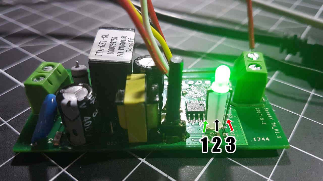
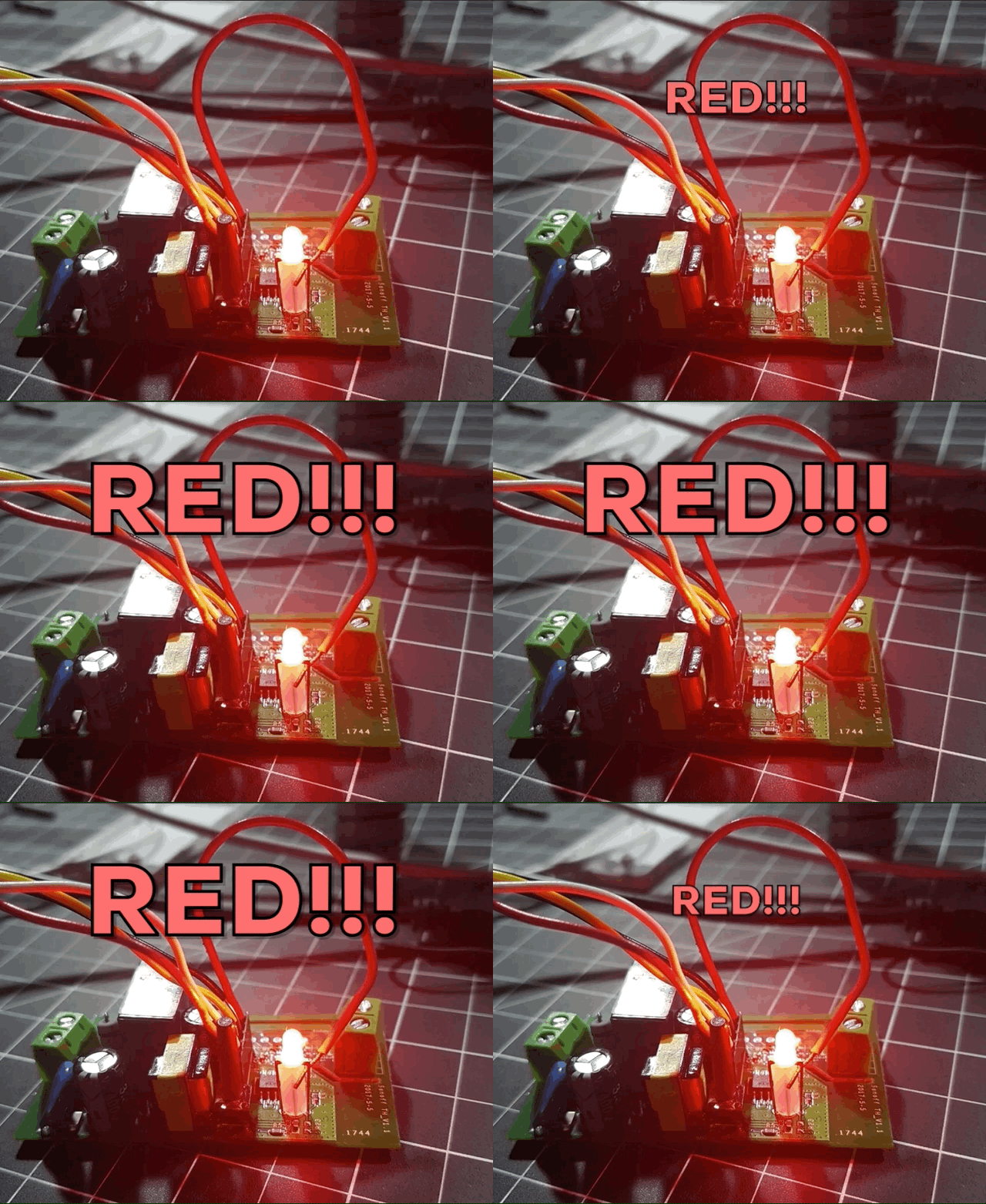
Hey! Look at that there LED. It’s got itself 3 legs! That usually means that it’s got 2 or more colors. Now judging by the way setting pin 13 to low causes the led to turn on, I’m going to assume that this is what’s known as a common anode LED. This means that the centre pin is always 3.3v and when you ground one of the other two, it turns that emitter on. Grounding the right pin turns the LED red. Let’s attach that to GPIO14 for now as we don’t have current plans for it.

That’s it for this round. Stay tuned for part 2 of the SONOFF saga. If you have any questions or corrections, feel free to leave a comment below!